
Low CTE FR-4 PCB Manufacturing for Through-Hole Reliability
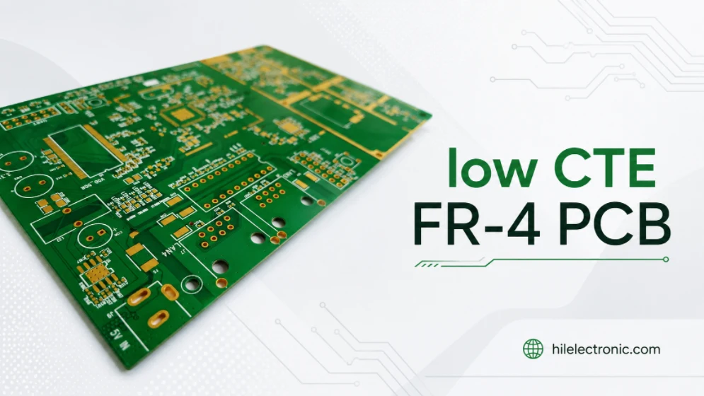
Low CTE FR-4 PCB manufacturing is used when a circuit board must control Z-axis expansion during lamination, soldering, lead-free assembly, thermal cycling, and long-term operation. Highleap Electronics is a PCB fabrication and PCB assembly factory. We do not manufacture laminate, prepreg, resin, or copper-clad material. Our role is to manufacture bare PCBs and PCB assemblies using customer-specified or customer-approved Low CTE FR-4 materials from qualified laminate suppliers.
In a real PCB or PCBA project, Low CTE FR-4 is usually selected to reduce plated-through-hole stress, improve multilayer reliability, support lead-free reflow, and maintain dimensional stability in high-layer-count or reliability-critical designs. The manufacturing work connects the material requirement with stackup control, lamination planning, drilling and plating reliability, DFM review, assembly process control, documentation, and repeat production traceability.
For projects where Low CTE FR-4 is part of a high-reliability build, the first engineering discussion usually belongs with multilayer PCB manufacturing rather than a generic FR-4 quote. The material affects how the board is sourced, laminated, drilled, plated, assembled, inspected, and kept consistent from prototype to production.
Low CTE FR-4 PCB Material Requirements for Production
A Low CTE FR-4 requirement should be treated as a reliability instruction, not as a generic material preference. In PCB manufacturing, CTE is directly connected with how much the laminate expands in the thickness direction during heat exposure. Excessive Z-axis expansion can increase stress on plated through holes, vias, inner-layer interfaces, resin systems, and solder joints.
The requirement may come from the fabrication drawing, customer AVL, reliability specification, automotive or industrial qualification plan, lead-free assembly requirement, or field failure history. Before production starts, the material callout should be connected to an approved laminate series, stackup, finished board thickness, layer count, hole structure, copper distribution, and PCBA process.
Material control starts from the drawing and approved stackup
The most useful drawings identify the intended material family, Tg level, CTE expectation, IPC slash sheet or customer specification, and whether approved equivalents are allowed. If the drawing only says “FR-4” while the product requirement expects Low CTE FR-4, the material decision should be clarified before CAM tooling and material purchasing.
Low CTE FR-4 should not be substituted with ordinary FR-4 after quotation unless the customer approves the change. The reverse also requires care. If a board was qualified with one specific Low CTE FR-4 material, changing to another low-CTE grade may still affect stackup thickness, dielectric values, drilling behavior, lamination response, impedance, and assembly reliability.
Typical applications of Low CTE FR-4 PCB
- High-layer-count multilayer PCBs
- Industrial control boards with long service life requirements
- Automotive electronics and EV-related control systems
- Networking hardware, backplanes, servers, storage, and telecom boards
- Boards with many plated through holes, vias, and press-fit connectors
- Lead-free PCBA projects with multiple thermal cycles
- Heavy copper or thermally stressed PCB assemblies
For these applications, the material choice is only one part of the reliability plan. Hole design, copper balance, lamination cycle, plating thickness, aspect ratio, soldering profile, and inspection requirements must also support the same reliability target. If the board is thick, complex, or close to a high-layer construction, the design team may also compare the requirement with 10-layer PCB materials and other multilayer material planning pages before the stackup is frozen.
Low CTE FR-4 Material Properties for PCB Design
Low CTE FR-4 is not one universal material. Different laminate suppliers offer different resin systems, glass styles, copper foil options, Tg values, Td values, dielectric properties, CAF resistance, and prepreg constructions. The selected supplier data sheet should be used for the final build, especially when controlled impedance, through-hole reliability, lead-free assembly, or repeat production is involved.
The table below gives practical engineering checkpoints for early discussion. Values should not be copied into a drawing without verifying the exact laminate and prepreg series that will be used for production.
Material data points engineers should verify before release
| Property | Typical review range or requirement | Why it matters for PCB manufacturing |
|---|---|---|
| Z-axis CTE before Tg | Often around 40 to 55 ppm/°C for many high-reliability FR-4 grades | Lower expansion helps reduce stress on plated through holes and vias during heat exposure |
| Z-axis CTE after Tg | Much higher than pre-Tg values and strongly material-dependent | Important for evaluating soldering stress, thermal cycling, and via fatigue risk |
| Tg | Commonly 170°C to 190°C for high-reliability FR-4 families, depending on grade | Affects resin stability and expansion behavior during lead-free assembly |
| Td | Often above 340°C for reliability-focused FR-4 materials | Helps evaluate resistance to thermal decomposition during fabrication and soldering |
| T260, T288, or T300 | Supplier-specific delamination performance | Useful when the board sees multiple lamination cycles, high copper weight, or severe assembly heat |
| CAF resistance | Often enhanced in high-reliability low-CTE grades | Important for dense via fields, fine spacing, high humidity, and long service life |
| Dk and Df | Use actual data sheet values by frequency and resin content | Needed for controlled impedance, signal integrity, and high-speed routing decisions |
| Copper foil and glass style | HTE, RTF, VLP, spread glass, and other options may be available depending on supplier | Affects signal loss, mechanical stability, drilling, and material availability |
Low CTE alone does not guarantee a reliable PCB. The approved build should combine suitable laminate properties with manufacturable hole design, controlled plating, balanced copper, clear stackup notes, proper surface finish, and a PCBA process that does not exceed the material’s practical thermal capability. Core and prepreg details should be checked early because prepreg material for multilayer PCB affects resin flow, dielectric thickness, lamination behavior, and final stackup control.
Low CTE FR-4 PCB Fabrication for Through-Hole Reliability
The strongest reason to specify Low CTE FR-4 is often through-hole and via reliability. When the board expands during heat exposure, copper barrels and inner-layer connections experience mechanical stress. Lower Z-axis expansion gives the design a better material foundation, but fabrication quality still decides whether that reliability can be achieved in production.
In fabrication, the material requirement must be connected with drilling, desmear, electroless copper, copper plating, inner-layer registration, hole wall inspection, and thermal stress testing when required. A low-CTE laminate cannot compensate for poor hole design, excessive aspect ratio, unbalanced copper, or unclear plating notes.
Fabrication controls that support low-CTE reliability
- Aspect ratio and finished hole size review
- Plated-through-hole copper thickness control
- Via design, annular ring, and resin recession checks
- Inner-layer registration and lamination alignment
- Cross-section or microsection inspection when specified
- Thermal stress or solder float testing when required by the customer
For boards with heavy copper, high current, or repeated heat exposure, the material review may also connect with PCB thermal management techniques. Thermal design and CTE control are not the same topic, but they often meet in the same high-reliability product.
Low CTE FR-4 Stackup Control for High-Layer-Count Boards
Low CTE FR-4 stackup control is important because multilayer reliability depends on the full construction, not only the laminate name. Core thickness, prepreg selection, resin content, glass style, copper distribution, reference planes, finished thickness, and lamination cycle all influence the finished board.
For high-layer-count boards, the stackup should be approved before CAM tooling. If controlled impedance is required, dielectric thickness and Dk values should be matched to the selected material series rather than estimated from generic FR-4 assumptions.
Stackup data that should be fixed before CAM tooling
- Core and prepreg material series
- Finished board thickness and tolerance
- Copper weight by layer and finished copper requirement
- Dielectric thickness between signal and reference layers
- Impedance target, tolerance, and coupon requirement
- Sequential lamination, buried via, or blind via requirements
When impedance control is part of the project, the Low CTE FR-4 material should be reviewed together with PCB impedance control. A stackup that is reliable mechanically but not aligned with the impedance table can still create production delays or electrical mismatch after fabrication.
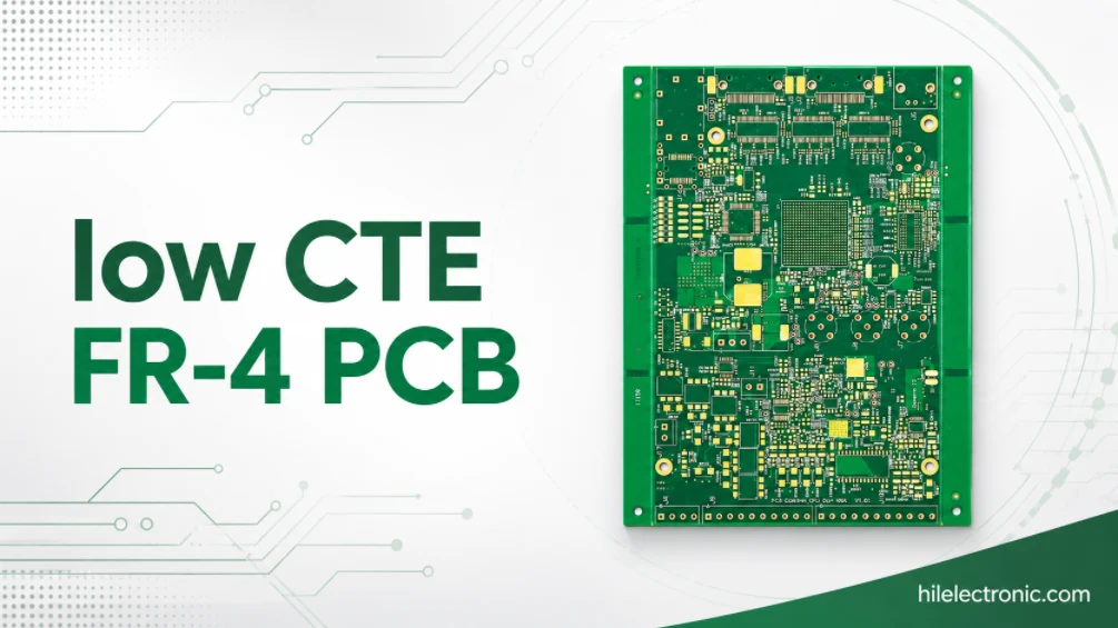
Standard FR-4 vs Low CTE FR-4 for Reliability-Critical PCB Projects
This comparison is useful when a drawing, AVL, qualification record, or reliability plan calls for Low CTE FR-4 and the project team needs to understand how that requirement affects sourcing, fabrication, assembly, inspection, cost, and lead time. It should not be used to justify an unapproved material substitution.
The comparison also helps when a customer allows approved equivalents. In that case, equivalent materials should be checked against actual data sheets, stackup requirements, customer approval rules, and production history. Cost and availability questions should be handled as part of the same engineering review, not separated from the material approval process.
Engineering comparison for material approval and manufacturing risk
| Comparison item | Standard FR-4 | Low CTE FR-4 | PCB manufacturing implication |
|---|---|---|---|
| Z-axis expansion | Depends on the selected FR-4 grade and Tg level | Selected to better control thickness-direction expansion | Improves the material basis for plated-hole and via reliability |
| Lead-free assembly margin | Must be verified by Tg, Td, and assembly profile | Often paired with high Tg and higher thermal reliability | Useful for multiple reflow cycles, large components, and mixed assembly processes |
| Through-hole reliability | Suitable for many standard products | Preferred when plated holes face stronger thermal or mechanical stress | Review drilling, plating, aspect ratio, copper thickness, and inspection together |
| High-layer-count builds | Can be used when reliability margin is adequate | Often selected for thicker and higher-reliability multilayer PCBs | Stackup, lamination, copper balance, and registration should be reviewed before tooling |
| Impedance and SI | Use actual Dk and dielectric thickness | Use the selected low-CTE grade data sheet, not generic FR-4 assumptions | Controlled impedance values may need recalculation after material selection |
| Cost and availability | Usually broader availability and lower cost | May require specific material sourcing and longer confirmation | RFQ should state approved material series, alternates, and documentation needs |
Low CTE FR-4 is not automatically required for every PCB. It becomes valuable when the product risk justifies tighter control over expansion, plated-hole stress, thermal cycling, and repeat manufacturing consistency. If the discussion is mainly about general FR-4 cost pressure rather than reliability requirements, the purchasing team may also review FR-4 PCB cost increase to separate market pricing from engineering material selection.
Low CTE FR-4 Laminate Suppliers and Approved Material Control
Real PCB purchasing rarely stops at the phrase “Low CTE FR-4.” Many B2B programs require an approved supplier, a named laminate series, an IPC slash sheet, a customer AVL, or an equivalent-material approval rule. A PCB factory should follow that rule when sourcing laminate and prepreg for production.
Highleap Electronics can build with customer-specified or customer-approved Low CTE FR-4 materials. The material itself is supplied by qualified laminate manufacturers, while the PCB fabrication and assembly process is controlled by the production package, drawing notes, stackup, and quality requirements.
Common material families discussed in low-CTE FR-4 projects
Low-CTE or high-reliability FR-4 discussions may include materials from suppliers such as Isola, Shengyi, ITEQ, Kingboard, Nan Ya, EMC, Panasonic, Ventec, and other qualified manufacturers. Examples often discussed in high-reliability FR-4 projects include Isola 370HR PCB, Isola FR408HR, Shengyi S1000-2M PCB materials, ITEQ IT-180A, Kingboard KB-6167F, Nan Ya NP-175F, and similar approved grades. The exact choice should follow the customer drawing, AVL, stackup, electrical requirement, reliability target, and material availability.
- Customer-specified material series and approved vendor list
- Equivalent material review only with customer approval
- Core and prepreg availability for the required thickness
- Copper foil type, copper weight, and glass style options
- Material certificate, compliance statement, or traceability requirements
If a project has already passed validation with one material series, changing to another low-CTE material should be handled as an engineering decision. Even when both materials are described as Low CTE FR-4, they may not have identical Dk, Df, resin content, prepreg flow, drilling behavior, copper foil options, or lead time. For Kingboard-based builds, nearby material pages such as KB-6160 PCB laminate and KB-6165 PCB laminate can support internal material comparison without replacing the customer-approved specification.
Low CTE FR-4 PCB Assembly and Thermal Stress Control
Low CTE FR-4 is often selected because the assembled board must survive real soldering and service conditions. Bare-board reliability and PCBA reliability should therefore be reviewed together. A strong laminate choice can still be weakened by poor pad design, unsuitable surface finish, excessive reflow exposure, uneven copper distribution, or unclear inspection requirements.
For turnkey PCBA projects, the material requirement should be visible in the fabrication drawing and carried into the assembly plan. SMT, through-hole soldering, selective soldering, press-fit insertion, conformal coating, and final test can all interact with the board material and stackup. When customers need bare board and assembly from one source, the project should be planned through PCB assembly services instead of treating PCBA as a late add-on after fabrication.
Assembly checks for thermally stressed Low CTE FR-4 boards
- Lead-free reflow profile and number of thermal cycles
- Large BGAs, connectors, power devices, and high-thermal-mass components
- Pad design, solder mask opening, via-in-pad, and thermal relief
- Surface finish selection such as ENIG, immersion silver, OSP, or HASL lead-free
- Press-fit connector zones and plated-hole requirements
- AOI, X-ray, ICT, functional testing, or cross-section inspection when required
The most reliable assembly plan is built before the bare board is frozen. If the material, surface finish, via structure, copper weight, and assembly process are reviewed together, fewer problems return later as soldering issues, reliability concerns, or engineering holds.
Low CTE FR-4 PCB Quote and Documentation Requirements
A useful Low CTE FR-4 PCB quote should price the real reliability requirement, not only the board size and layer count. Material sourcing, lamination, drilling, plating, impedance, assembly, inspection, and documentation can all change the cost and lead time.
If the project only includes Gerber files without a fabrication drawing, it may be impossible to confirm whether Low CTE FR-4 is required, which laminate series is approved, whether alternates are allowed, and what inspection records are expected. These details should be provided before quotation when possible.
RFQ files needed for accurate production review
- Gerber, ODB++, or IPC-2581 files
- Fabrication drawing with Low CTE FR-4 material callout
- Stackup drawing with core, prepreg, copper, and finished thickness
- Approved material series or accepted equivalent rule
- Controlled impedance table if required
- Finished copper weight, hole size, aspect ratio, and plating requirements
- Surface finish and solder mask requirements
- BOM, pick-and-place file, assembly drawing, and test instructions for PCBA
- Certificate, traceability, cross-section, or reliability report requirements
- Prototype quantity, expected production volume, and target lead time
Complete files allow the engineering team to separate true manufacturing limits from missing documentation. For repeat production, the approved material, stackup, process notes, inspection requirements, and assembly conditions should be kept consistent unless the customer approves a controlled change. When the data package is ready, submit it through the Highleap quick quote form for manufacturing and assembly review.
Low CTE FR-4 PCB FAQ
The questions below address common engineering and purchasing concerns before a Low CTE FR-4 PCB or PCBA project moves into quotation, fabrication, or assembly.
What is Low CTE FR-4?
Low CTE FR-4 is an FR-4 laminate and prepreg system designed to reduce thermal expansion, especially in the Z-axis direction. It is used when the PCB needs better through-hole reliability, lead-free assembly margin, thermal cycling performance, or multilayer stability than a generic FR-4 build may provide.
Why is Z-axis CTE important in PCB manufacturing?
Z-axis CTE controls how much the board expands through its thickness during heat exposure. This matters because plated through holes and vias must survive expansion and contraction during lamination, soldering, and field operation. Lower Z-axis expansion can help reduce stress on copper barrels and inner-layer connections.
Does Low CTE FR-4 replace high Tg FR-4?
No. Low CTE and high Tg are related reliability considerations, but they are not the same property. A material may be selected because it combines high Tg, low CTE, high Td, CAF resistance, and lead-free assembly compatibility. The selected data sheet should be checked instead of relying on one keyword.
Can Low CTE FR-4 replace standard FR-4?
It can be used when the project requirement justifies the change, but substitution should be approved by the customer. Changing from standard FR-4 to Low CTE FR-4 can affect stackup, impedance, sourcing, cost, lead time, and product qualification.
Which laminate suppliers provide Low CTE FR-4 options?
Low-CTE or high-reliability FR-4 options are available from major laminate suppliers such as Isola, Shengyi, ITEQ, Kingboard, Nan Ya, EMC, Panasonic, Ventec, and other qualified manufacturers. The exact material should follow the customer drawing, AVL, data sheet, and approved stackup.
Is Low CTE FR-4 suitable for lead-free PCB assembly?
Many Low CTE FR-4 grades are selected for lead-free PCBA projects, but assembly compatibility should still be verified against the selected material, Tg, Td, reflow profile, number of thermal cycles, component thermal mass, and inspection plan.
What should be included in a Low CTE FR-4 PCB quote request?
The RFQ should include Gerber or ODB++ files, fabrication drawing, approved material callout, stackup, controlled impedance table if needed, copper weight, surface finish, hole requirements, inspection expectations, quantity, lead time target, and assembly files if PCBA delivery is required.
Request a Low CTE FR-4 PCB Engineering Review
Low CTE FR-4 PCB manufacturing is most effective when material selection, stackup control, via reliability, lead-free assembly, and documentation are aligned before production. Highleap Electronics can support prototype, pilot, and repeat production builds using customer-specified or customer-approved Low CTE FR-4 materials from qualified laminate suppliers.
To start a Low CTE FR-4 PCB or PCBA review, prepare your Gerber or ODB++ files, fabrication drawing, stackup, material callout, impedance table, BOM, pick-and-place file, expected quantity, and any required inspection or traceability documents. Submit the package through the Highleap quick quote form for manufacturing and assembly review.

Recommended Posts

Taconic RF 35 vs RO4350B PCB
Table of contentsRF-35 vs RO4350B Procurement and...

TMM4 Filter PCB Manufacturing
TMM4 filter PCB manufacturing is controlled by the...

TMM3 PCB Manufacturing for RF Modules
TMM3 PCB manufacturing is most useful where the RF module...

TMM6 PCB Fabrication
TMM6 fabrication is the process-control page for a mid-Dk...
How to get a quote for PCBs
Let’s run DFM/DFA analysis for you and get back to you with a report. You can upload your files securely through our website. We require the following information in order to give you a quote:
-
- Gerber, ODB++, or .pcb, spec.
- BOM list if you require assembly
- Quantity
- Turn time
For PCBA services, please provide your BOM (Bill of Materials) and any specific assembly instructions. We also offer DFM/DFA analysis to optimize your designs for manufacturability and assembly, ensuring a smooth production process.